Upgrading the standard air intake system to match actual climate and operating conditions improves efficiency and ensures stable gas turbine operation
Expertise
- Developing mathematical models to assess energy effects
- Numerical calculations and simulations of gas turbine operation
- Analysis of how air treatment quality affects gas turbine output and efficiency
- Analysis of power equipment performance on the wholesale electricity market
- Developing financial models (NPV, IRR, DPP)
- Assessment of capital and operating costs
- Analysis of risks and alternative project scenarios
- Development of technical solutions and layouts
- Design of steel structures, piping and automation systems
- Equipment selection
- Preparation of the full set of working documentation in line with applicable safety rules, codes and standards
- Fabrication and installation of steel structures
- Installation of main and auxiliary equipment
- Piping and main equipment tie-ins
- Electrical installation and instrumentation
- Acceptance testing
- As-built documentation
- Guarantee testing confirming the specified parameters are achieved
- Performance monitoring
- Supply of spare parts and consumables
- Scheduled preventive maintenance, replacement and upgrade of components
our approach to air intake retrofit
-
Air heating system upgrade
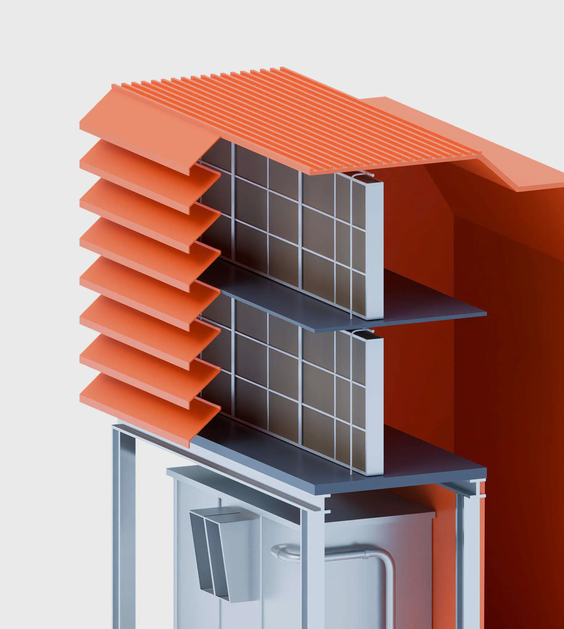
 Air temperature at the compressor inlet has a significant impact on the technical and economic performance of gas turbines and combined cycle units.
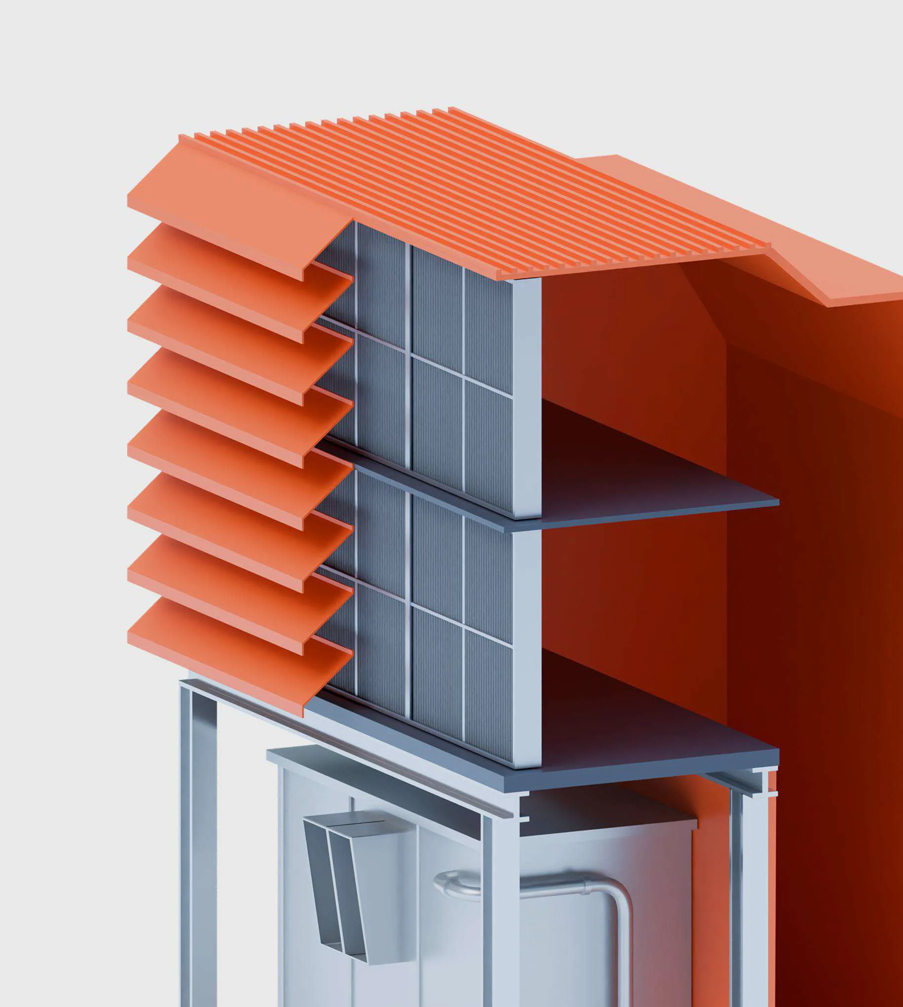
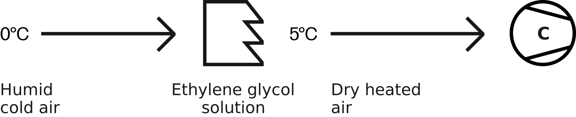
The air heating system prevents icing of the air intake components and the compressor inlet area. Heating takes place in heat exchangers, where the heat carrier is a water-ethylene glycol solution heated by district heating water.
A properly working system ensures stable gas turbine operation at low temperatures and high humidity.How it works
Reasons to upgrade
- No heat exchangers
- Insufficient heat exchanger capacity
- No clear understanding of the optimal heating temperature
-
-
Air cooling system installation
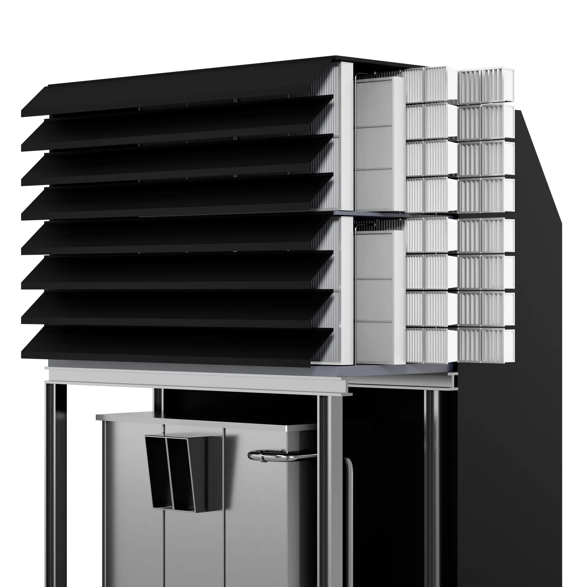
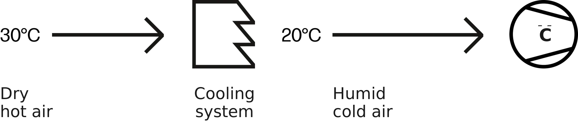
 An evaporative air cooling system lowers the air temperature and increases its density and mass flow at the compressor inlet. The technology is simple in design and cost-effective in capital expenditure.
Lowering the compressor inlet air temperature by just 1 °C increases output by 0.5–0.8%, so the system pays off quickly through higher electricity sales revenue and fewer underproduction penalties.How it works
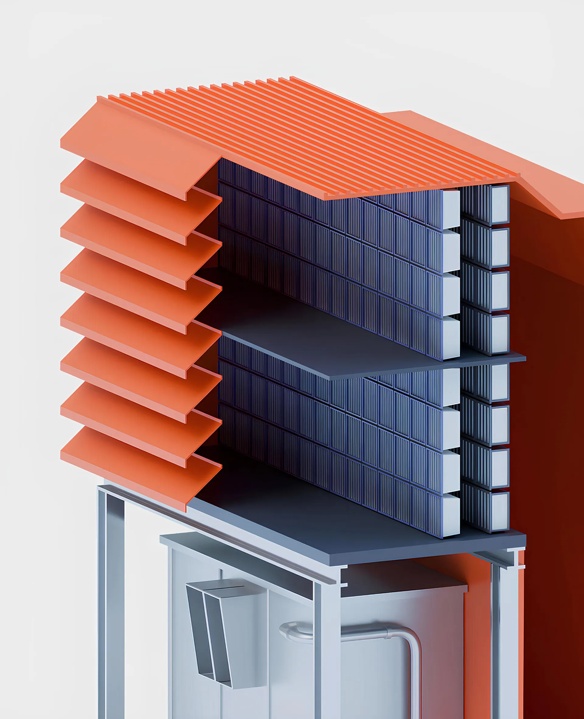
System layout
- Evaporative modules
- Inertial droplet separator
- Cooling media cassettes
- Piping and valves
- Process control systems and instrumentation
- Service platform
- Pump unit with storage tank
-
-
Filtration system efficiency improvement
 Compressor fouling is a key factor, accounting for up to 70–85% of total gas turbine operating losses. Insufficient efficiency of standard filtration systems accelerates deposit build-up on the blades, reducing corrected and available output, degrading compressor aerodynamics and, as a result, the overall performance of the gas turbine.
Choosing the optimal air filtration layout for the climate and operating conditions is a complex technical and economic task that requires balancing capital costs, the technology concept and gains in operating efficiency.Reasons to upgrade
- Heavy fouling of the flow path and performance degradation of the gas turbine
- Corrosion and erosion wear of the inlet guide vanes (IGV) and the first compressor stages
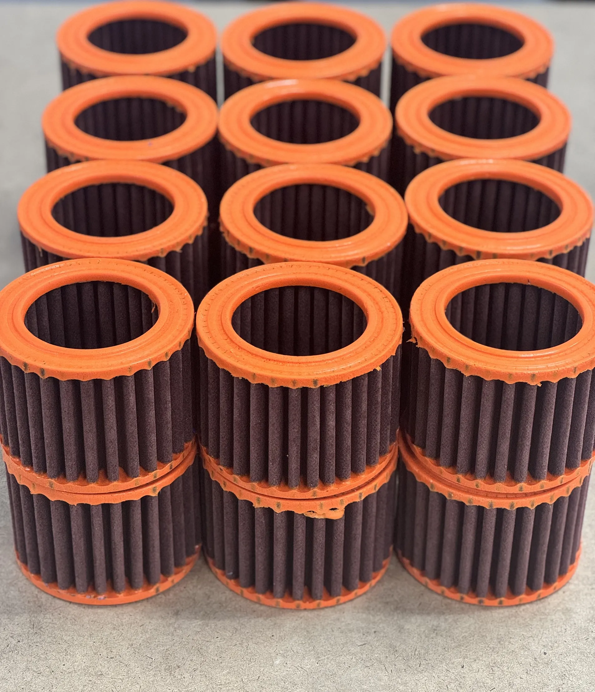
- Short service life of standard filter elements
- Significant operating costs of washing and equipment downtime
-
-
Aerodynamic optimization
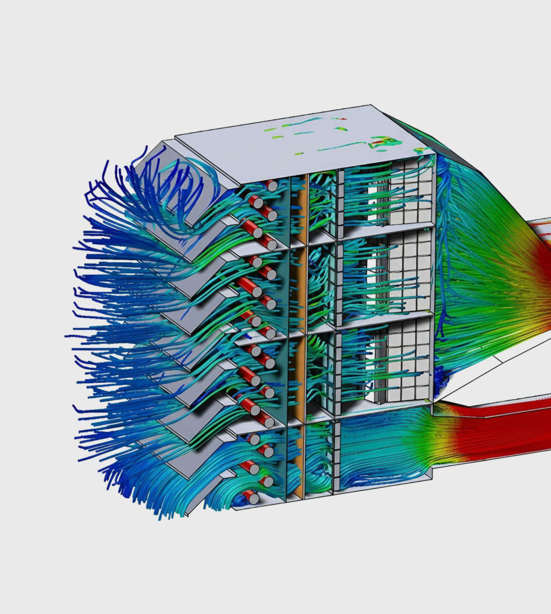 Air intake pressure loss directly affects the available output and fuel efficiency of a gas turbine. Higher intake resistance lowers the compressor inlet pressure, which reduces air mass flow and degrades overall gas turbine performance.
Modern CFD modeling enables detailed and highly accurate aerodynamic analysis of air intake systems. The modeling examines velocity and pressure fields along the cross-section and length of the duct, zones of increased local losses, non-uniform velocity profiles at the compressor inlet, and turbulent structures and their effect on flow stability.Stages
- Collection and verification of input data
- 3D model of the air intake duct
- CFD analysis of the existing design: calculation of pressure and velocity fields
- Development of engineering solutions and recommendations
- Feasibility study
-